Topological optimization is routinely used in the design and refinement of microfluidics devices. The process also comes in handy for modeling a Tesla microvalve.
What Is a Tesla Microvalve?
The Tesla microvalve is a valve that allows fluid to flow freely in one direction but not in the reverse. This valve is one of the many inventions designed by the famous late Nikola Tesla. In recognition of Tesla’s 158th birthday anniversary, my colleague Fanny Littmarck wrote about his life and many contributions to science and engineering. She did not mention the microvalve, however. Perhaps because it is often overshadowed by his electrical inventions.
What makes this valve so fascinating is the fact that it has no moving mechanical parts. This design greatly reduces the risk of wearing out or breaking down. You may be asking yourself, “Well, how does the valve stop fluid without any moving parts?” Interestingly enough, the valve’s fixed geometry inhibits reverse flow through the utilization of friction forces. Thanks to the design, the fluid itself becomes the inhibiting force.

Tesla microvalve schematic from Tesla’s “Valvular conduit” patent. Inlet on the right end, outlet on the left end.
To achieve this effect, the microvalve design can be optimized by dispersing a distinct amount of material within the modeling domain.
Optimizing the Tesla Microvalve Design
When modeling microfluidic devices, topological optimization is often used to refine the model. The Topological Optimization of a Tesla Microvalve model serves as an exceptional example of how you can do just that, using COMSOL Multiphysics together with the Microfluidics Module. In the case of a Tesla microvalve, you can gauge the effectiveness of your design by obtaining the ratio of the pressure drop between the inlet and outlet for both forward and reverse flows.
By checking out the model, you will learn how to work with two laminar flow interfaces, one for the forward flow and another for the reverse. Additionally, you will see how two instances of the Navier-Stokes equations are computed for the same flow types.
In this example, the optimized design has a triangular-shaped material placed close to the outlet, allowing the forward flow to bend around it. This results in a low pressure drop between the inlet and outlet.
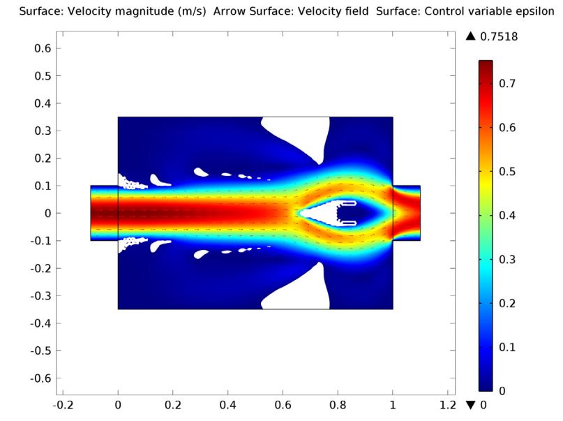
Forward flow in the optimized design after 150 iterations.
In the reverse direction, the flow meets the triangular material’s flat edge, causing the backward flow’s velocity to reroute upwards and downwards toward the device’s walls. The redirected flow’s path is further impeded as it is forced toward additional obstacles.

Reverse flow in the optimized design.
Using a global evaluation, the ratio of the pressure drop between the forward and reverse flow is computed. The value is approximately 1.85.